The model that we have defined above is called a basic "parent" model. By default, the boundary conditions on these models are assumed to be no flow and the model results are often not very accurate near the model boundaries. However, knowing that the parent model is more accurate away from the boundaries, we can use smaller, nested “child” models to get more details (model resolution) in the areas of interest, using the flow information from the parent model to assign boundary conditions to the child model. The procedure to do this is presented in this Section.
Begin by going to Zones and then ZoneRect as shown in Figure 29. Then construct a rectangular area such as shown in Figure 30 in the same fashion that we created the model domain: use a click to indicate the position of this first vertex of the rectangle, then click the cursor at the location of the vertex that is diagonal from your initial vertex ("the opposite corner"). Click ‘SaveShape’ to finalize the geometry; this action automatically launches the Zone Attributes menu shown in Figure 31.
Note that the submodel boundary in this example is relatively close to the left (western) boundary of the parent model, which we typically try to avoid; however, in this case, the western boundary corresponds to the edge of a large surface water body that is a dominant surface seep, making the model more accurate than in the case of no surface water body corresponding with the boundary.
In the default tab (Flow Property), there is a box next to “Submodel Domain” under the Zone Types subsection. Check this box and click ‘SAVE’ to tell MAGNET to use the zone as the simulation domain. However, before the zone will be recognized as the simulation domain, an important distinction must be made in the Domain Attributes menu: go to Conceptual Model, then Domain Attr, then access the Simulation Settings and put a check mark in the box adjacent to Boundary Condition from Parent Model (Figure 32). To proceed with the nested submodel simulation, click SIMULATE.
Also note that it is possible to draw an entirely new model domain using the DrawDomain tools but still use parent model results to assign boundary conditions in the new, smaller model, but the parent model will be “lost”. Using a zone feature to represent a nested submodel allows the user to retain the regional model domain.
A series of three windows are presented in succession as shown below as Figure 33, Figure 34, and Figure 35, and you click OK to each. By clicking on the last of the three, the simulation begins.
The submodel solution is presented in Figure 36. If the no-flow boundaries imposed on the “parent” model were active in the “nested” model, the contours would be orthogonal to the boundaries of the “nested” model. But they are not because the nested model uses constant head boundaries derived from the “parent model”.
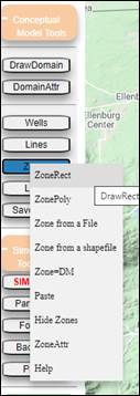
Figure 29: Sequence of steps to access ability to draw nested model with a Zone feature
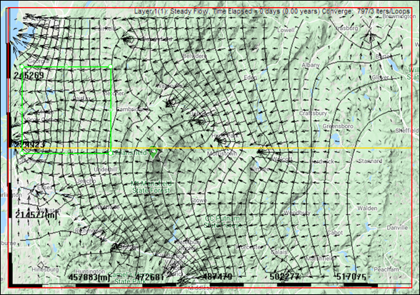
Figure 30: Rectangular "nested" model in area of "Parent" model.
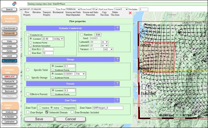
Figure 31: Assigning a Zone feature as the Submodel Domain for subsequent simulations.
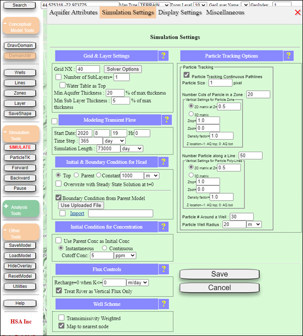
Figure 32: Domain Attributes window to specify that boundary conditions will come from the Parent Model.
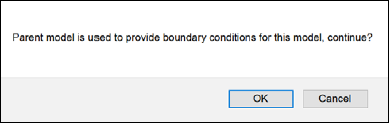
Figure 33: Confirmation prompt associated with “nested” model application.
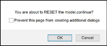
Figure 34: Prompt to confirm that you will move on to a new simulation.
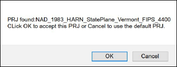
Figure 35: Prompt indicating the suggested projection (select OK to use the suggested projection; or cancel to use your own projection identified in the Domain Attributes menu.
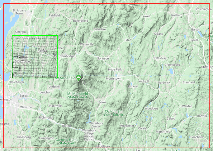
Figure 36: Solution to problem defined on "nested" model