When a well is used for drinking water supply (or even irrigation water), it is often necessary to delineate a wellhead protection area, or an area beneath which water is contributing to the well. The rationale is that potential sources of contamination up-gradient from the well can be identified and mitigated or eliminated.
In MAGNET, we can delineate a wellhead protection area by adding particles to a well and trace backwards from the well along the flow pathlines. In section 4.2, we learned how to add particles along a line drawn in the model domain. The process for adding particles to wells is much easier. Simply click on the well marker (yellow “pushpin”) to open the Well Inputs Options menu. Find the box next to Add Particle and check it (see Figure 59). Then click OK. Particles will be placed in the immediate vicinity of the well, around the well, at the onset of the next simulation
Click SIMULATE and proceed through (click OK) the now familiar prompts regarding resetting the model, obtaining boundary conditions from the parent model, and using the identified projection system. Then you will see the prompt regarding forward versus backward tracking that we saw earlier (shown again in Figure 60). Click cancel to perform backward particle tracking.
When the groundwater model is finished running, particles will begin emanating backward from the well along the calculated flow field. The `envelope’ of particle pathlines gives an estimate of the groundwater source water area for a given period of time. The particle envelope will continue extending back along the flow field until the simulation period is over or the particles reach a boundary (see Figure 61).
We will next explore how particles can be used to model transport of chemicals. As a precursor once the particle tracking is completed, open up the Well Input Options menu once again, and uncheck the Add Particle box to remove particles from the well location. Click OK.
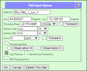
Figure 59: Well Input Options chart, with the ‘Add Paticle’ box checked so particles will be placed around the well at the onset of the next simulation.
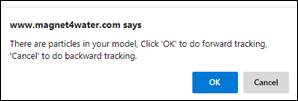
Figure 60: Prompt regarding whether to perform forward or backward particle tracking. For wellhead protection area delineation, we should use backward tracking (click Cancel).
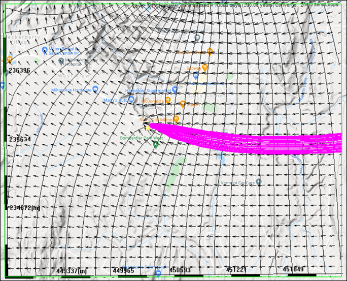
Figure 61: Well source water area as estimated from backward particle tracking. Note that the conceptual well feature (yellow marker) is slightly offset from the numerical well location, which is located at the nearest model node to the conceptual well feature. You can increase the grid size (NX) to reduce/eliminate the offset.