Let us now look at the impact of introducing a pumping or injection well into the simulation. This requires modeling with higher resolution (more detail). This can be achieved by modeling a smaller area, or by increasing the number of grid cells of the simulation `mesh’ as was explained in Section 5.1.
We will now adjust the size and location of the zone being used to define the submodel domain. Go to Other Tools, then Utilities, then Geometry unlocked to show the vertices (nodes) of the submodel zone (it may not be necessary if the zone is already unlocked). Click-drag on any of the nodes to adjust the submodel domain to cover the small, populated area south of the lake (see Figure 55). We will add a water supply well (pumping well) near the center of model.
To add a well to the model you click Conceptual Model Tools and then Wells. The following window will appear (Figure 56). Now click Draw Wells. A plus sign will appear that you can move with your mouse. Move the plus sign to the location where you wish to locate a well and click your mouse. The following window will appear (Figure 57). The inset window contains the information pertinent to the well you just located. You can now change the pumping rate from 0 to the value appropriate for this well in your model. There are several options but the one that you may need later is the specification of a particle. Later we will be using tracer particles to establish where groundwater flows in the model. Note that this is also where you can delete a well.
You are now ready to simulate the impact of a well in the area you have selected for your model. The same process you used earlier to simulate the behavior of the hydraulic head is repeated. If you click on SIMULATE under Simulation Tools you will see prompts regarding resetting the model and the model projection (accept to proceed).
The resulting flow field is shown in Figure 58. One can see the local convergence of groundwater and a head depression near the well in response to the pumping. If you examine the water balance, you will see that the well discharge is small compared to the other sources and sinks of water (recharge, flow in/out of the model boundary, and surface seepage).
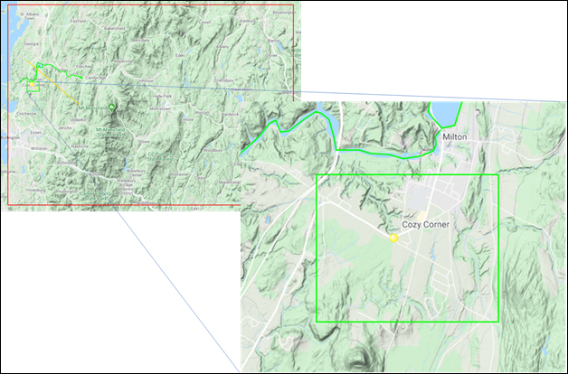
Figure 55: New submodel domain for a small populated area south of the lake near Milton.
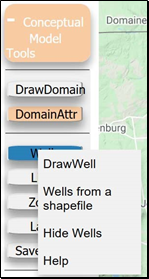
Figure 56: Opening Conceptual Model Tools to select a well location.
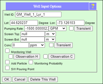
Figure 57: Pop up window generated upon selecting a well location. You use a negative number you are introducing a withdrawal well and if you use a positive number you are emplacing a recharge well. Type in a value and when done, click OK.
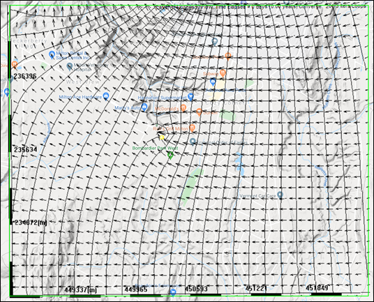
Figure 58: Simulated submodel results with the pumping (extraction) well turned on.