As noted, we have two kinds of layers and each has its own protocol for being added to the model. We will now add a geologic layer to the default condition of only one geologic layer. To add a geologic layer we go to Conceptual Model Tools, then Layers, and then Add a New Layer. Clicking Add a New Layer adds the layer we are seeking. It is added to the bottom of the model and has the same spatial extent as the top layer of the model. However, this layer can have a unique set of physical attributes such as hydraulic conductivity. Note that, if you make geometric changes to the top layer, all layers below it are appropriately adjusted.
Figure 71 shows the modeling environment after you have added a layer to the model. Clicking on the ‘v’ to the right of the word Layer in the Geolayer Name box reveals all the currently existing layers and if you click one of the other layers the information on the screen relates to that layer.
You can delete any layer by going to Conceptual Model Tools, then Layer, then click Delete Current Layer. You can add a third layer (Layer 3) and then delete it using this approach (see Figure 72).
We now need to set the attributes for Layer 2. Change to Layer 2 using the drop-down menu mentioned above, and then click Conceptual Model Tools, then DomainAttr. This opens the Domain Attributes menu for Layer 2 (see Figure 73). Reduce the hydraulic conductivity to 2 m/day and the aquifer thickness to 10m (33ft). Note that you can navigate between layers from within the Domain Attributes menu (Aquifer Attributes tab) by using the drop-down menu called GeoLayer near the top.
We next need to add the submodel zone to both layers to be able to properly simulate the 2-layer submodel. This is done by `copying and pasting’ the zone from Layer 1 to Layer 2. Begin by navigating to Layer 1 and then accessing the Zone Attributes menu. You can access this menu through the ZoneAttr button (Conceptual Model Tools, then Zones, then ZoneAttr - Figure 74 ), as we discussed in section 5.3. Or, you can go to Utilities, then Unlock Geometry, and then click inside of the submodel zone in the map display.
Once you access the Zone Attributes menu for the submodel zone, find the `Copy this Zone’ option along the top menu ribbon/tabs. Click it to tell MAGNET to copy the zone to the MAGNET `memory’ (or clipboard) (see Figure 75). Now change to the second layer of your model so you can `paste’ the zone feature. To do this, click Conceptual Model Tools, then Zones, then Paste (see Figure 76). A prompt will appear telling you that only the geometry will be copied (no attributes) - click OK (Figure 77). The Zone Attributes menu will appear for the new zone added to the second Layer (Figure 78); make sure to check the box next to ‘Submodel Domain’ and then click SAVE.
Click SIMULATE to solve the new, two-layer groundwater flow and transport model, clicking through the usual set of prompts so that the simulation moves forward. We can view the plan-view results in each layer by switching back and forth using the drop-down menu at the top of the mapping/modeling environment. If we view the results in cross-section view, we can clearly see a second layer add to the model and the difference in groundwater velocities between the two layers (see Figure 79).
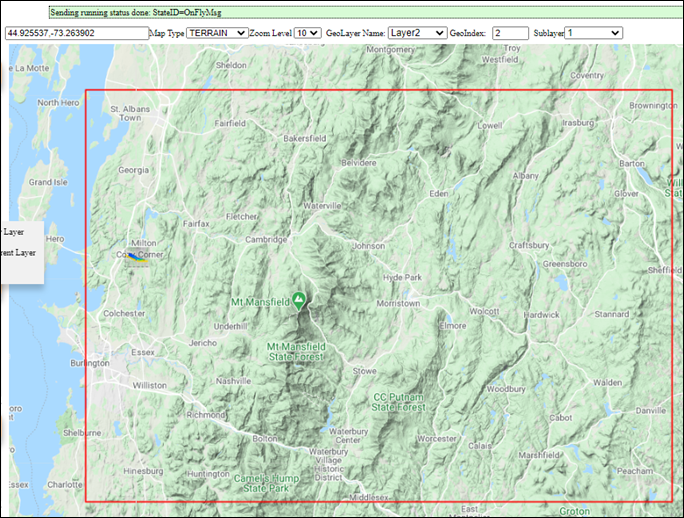
Figure 71: Window with a 2nd layer added, showing at the top information regarding the layers.
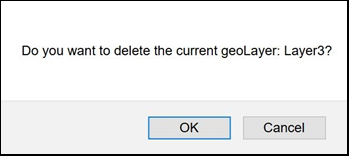
Figure 72: Warning associated with removing a geolayer (stratigraphic layer).
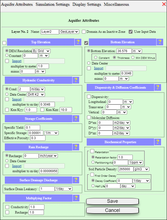
Figure 73: Aquifer Attributes geologic Layer2.
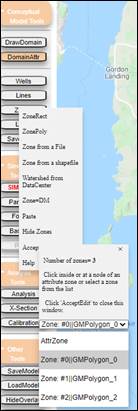
Figure 74: Process for accessing the attributes menu of the zone use as the submodel domain.
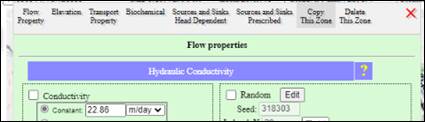
Figure 75: Window for copying a Zone feature to the MAGNET “memory” (or “clipboard”).
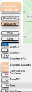
Figure 76: Buttons to click to paste a zone from the MAGNET memory/clipboard.
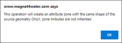
Figure 77: Prompt regarding how the pasted zone does not include any of the attributes from the original zone.
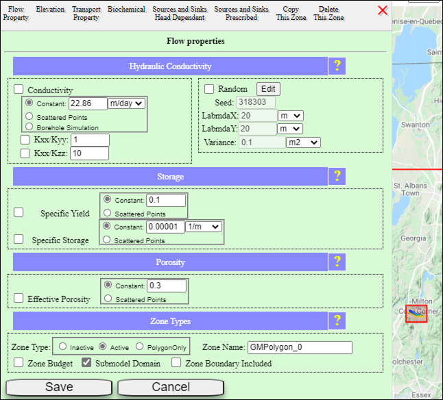
Figure 78: Submodel zone for the second geologic layer of the model.
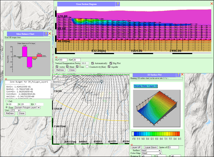
Figure 79: Simulation results for the secondlayer model.